Energy Chain for Machine Tool: A Practical Selection Guide
What an Energy Chain Does on a Machine Tool
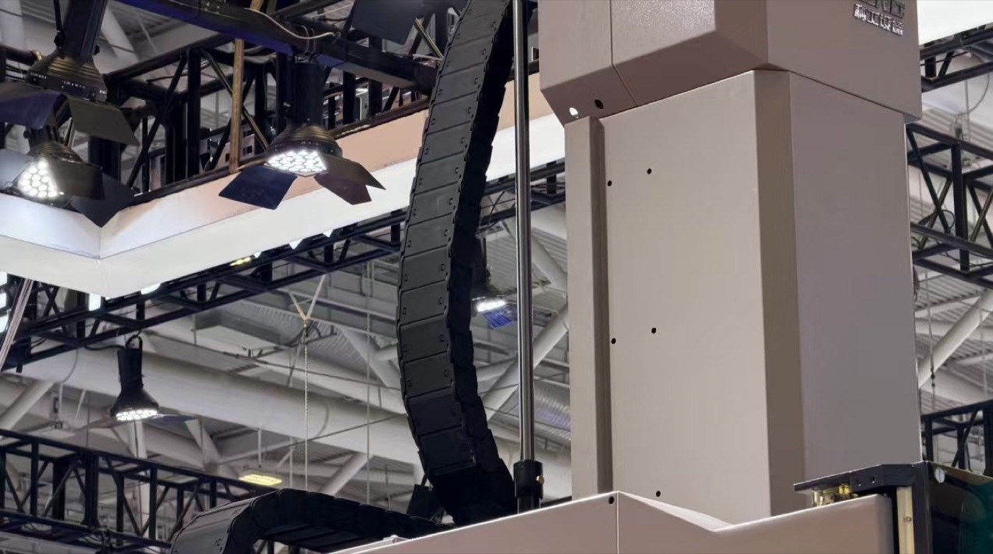
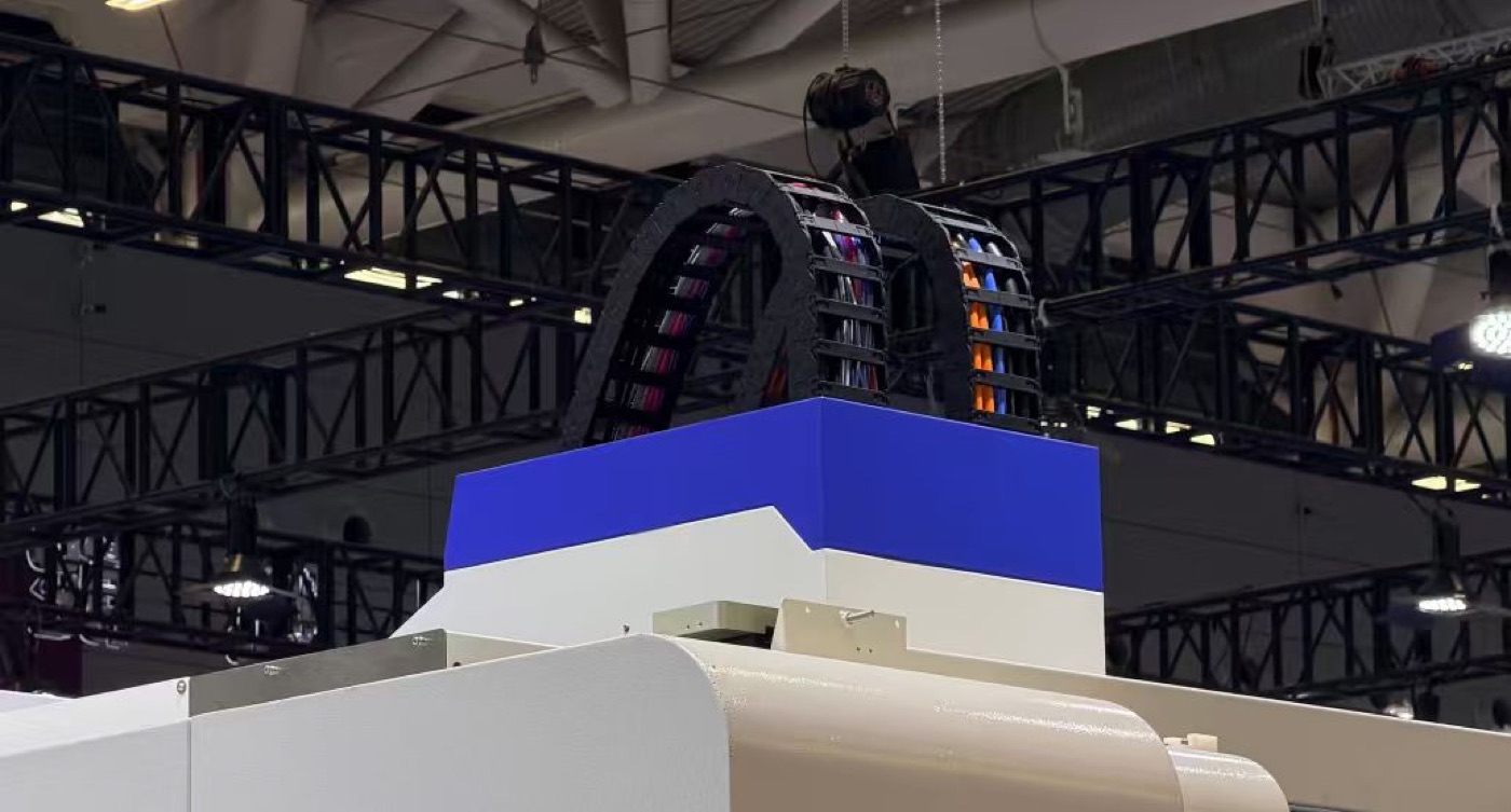
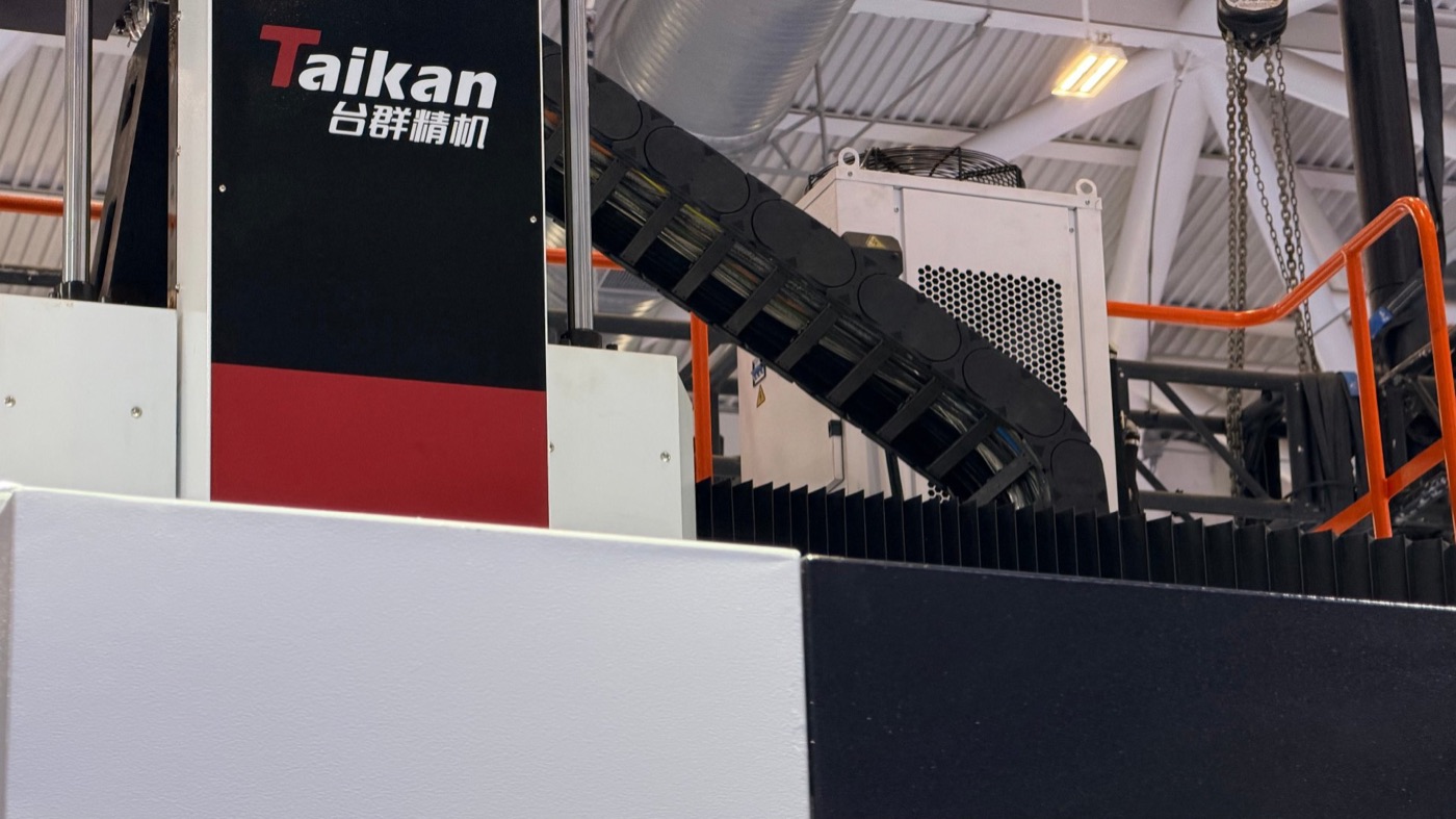
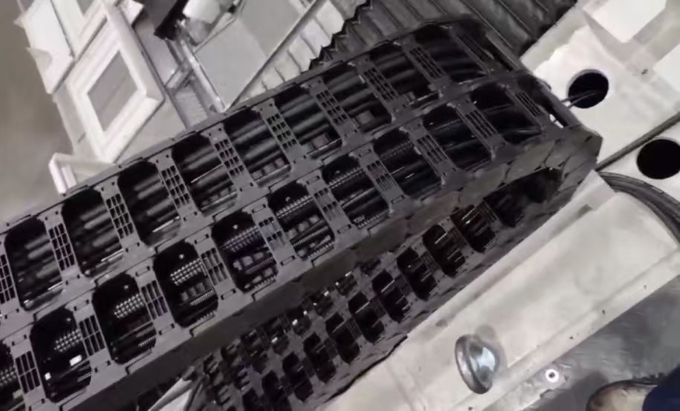
An energy chain for machine tool duty carries every cable and hose that feeds a moving axis — servo power, spindle cooling, encoder feedback, air and hydraulic lines — and holds each of them at a bend radius it can survive for millions of strokes. The chain itself is rarely the part that fails first. What fails is a cable that was allowed to bend tighter than its own datasheet permits, or a hose that rubbed against a neighbour for eighteen months. The energy chain exists to make both impossible: it fixes the bend radius, separates the conductors, and takes the tensile load off the cable jackets through proper strain relief at the moving end.
Energy Chain, Cable Carrier, Drag Chain: One Part, Three Specifications
Buyers in different markets use three names for the same hardware. The difference is not the plastic link — it is what the name implies you will be given.
- Energy chain is normally quoted as a system: chain, separators, strain relief, mounting brackets and, on long or fast travel, a guide trough.
- Cable carrier is the neutral term and the one used on most machine tool drawings. It says nothing about how the chain is supported.
- Drag chain is the term most common in Asian supply chains, and is often ordered by link size alone.
Order by link size and you may receive a chain that fits but a system that does not. Ask for inner height, inner width, bend radius and load capacity per metre as four independent values, then check how the chain is supported over your travel. That single question separates a supplier who sells links from one who understands axes.
Four Numbers That Fix the Size
Almost every machine tool energy chain is defined by four values. Get them right and the rest is detail. Get one wrong and no amount of careful installation will protect the cables.
| Value | How it is set | Typical range on machine tools |
|---|---|---|
| Inner height | Tallest cable or hose in the bundle plus about 10 % clearance | 25 – 75 mm on machining centre axes |
| Inner width | Sum of cable diameters, plus divider thickness, plus 10 – 20 % free space | 50 – 200 mm |
| Bend radius | Minimum bend radius of the stiffest cable, times a safety factor of 1.1 – 1.3 | 75 – 250 mm |
| Travel length | Half the machine stroke, plus the bend arc, plus an end margin at each fixing point | Set by the axis, not by the chain |
One point that causes more arguments than any other: the chain radius and the cable bend radius are measured from different reference points. A chain quoted at R100 does not put every cable at R100, and a stiff encoder cable in the outer layer of the bundle sees a larger radius than one in the inner layer. State the cable's own minimum bend radius in the enquiry and let the supplier do the conversion.
Matching the Chain to the Axis
Every axis type loads its chain differently, and a design that works on one will fail on another.
Vertical machining centre X, Y and Z
Short, fast strokes, usually bolted to the column or inside the enclosure. The chain spends most of its life folded, so joint wear in the arc is the dominant failure mode. Use a generous radius and a link with low-friction, hardened pins. Z-axis chains hang, so the cable bundle must be clamped so it cannot slide down through the chain.
Gantry and double-column machines
Long horizontal travel with a heavy bundle. Here the support method decides the outcome: self-gliding for moderate lengths, rollers or a guide trough once the unsupported span grows. Sagging upper runs that drag on the lower run will wear through cable jackets long before the chain itself is worn out.
Turning centres
The turret and tailstock axes are short but extremely fast, with coolant lines that stiffen when cold. Keep power and signal separated, and route coolant hoses in their own compartment so a leak cannot wash lubricant out of the chain joints.
Tool and pallet changers
Very high cycle counts and a tight envelope. Choose the smallest chain that satisfies the bend radius, not the smallest that fits, and check the cycle rating rather than the static load rating.
Installation Details That Decide Service Life
Chains rarely fail because the catalogue data was wrong. They fail because of five small installation decisions.
- The fixed end is not anchored rigidly, so the chain creeps sideways over the first months.
- Cables are pulled tight at the end of the stroke instead of being left with 10 – 20 % slack inside the chain.
- Heavy cables are stacked above light ones, crushing the small signal conductors in the bend.
- The bundle is not centred across the width, so the chain twists and wears its pins on one side.
- The guide trough is offset by a few millimetres — enough to wear the chain flank within a year.
All five are cheap to correct at commissioning and expensive to correct after the machine has shipped.
Signs the Chain Is Near the End of Its Life
Inspect the energy chain on the same schedule as the linear guides: overall elongation, wear marks on the side plates, pin clearance, and the condition of cable jackets in the arc. Elongation beyond 1 – 2 %, visible pin clearance or a chain that no longer sits flat in its trough mean the chain is close to replacement. Replacing a chain takes a few hours. Replacing a sheared encoder cable during a production run costs far more.
What to Send for a Quotation
- Travel stroke and the position of the fixed and moving ends
- Cable and hose list with outer diameters, weights per metre and minimum bend radii
- Travel speed and acceleration, and whether the chain runs horizontally, vertically or inclined
- The support available: self-gliding, rollers or guide trough
- Environment: chips, coolant, dust, dielectric fluid or ambient temperature above 60 °C
SONDA manufactures plastic and hybrid energy chains for machine tool axes, with modular dividers, custom bend radii and series that accept inner heights and widths as independent options — because machine tool axes rarely follow catalogue sizes. Send the five items above and you will get a chain and a mounting layout, not just a part number.
Specifying an energy chain for a machine tool axis?
Send us the stroke, the cable and hose list with diameters, the weight per metre and the bend radius you need. Our engineers reply with the chain system — series, inner height and width, dividers, strain relief and a guide trough if required — usually within one working day.
Power Chain for Machine Tool: Conductor Sizing and Chain Load
CCMT2026 Has Drawn a Clear Watershed of Transformation: Follow the Trend or Be Eliminated
Related Article