Cable Carriers for Large-Format Machine Tools: Long Travel, Wide Gantries and Heavy Bundles
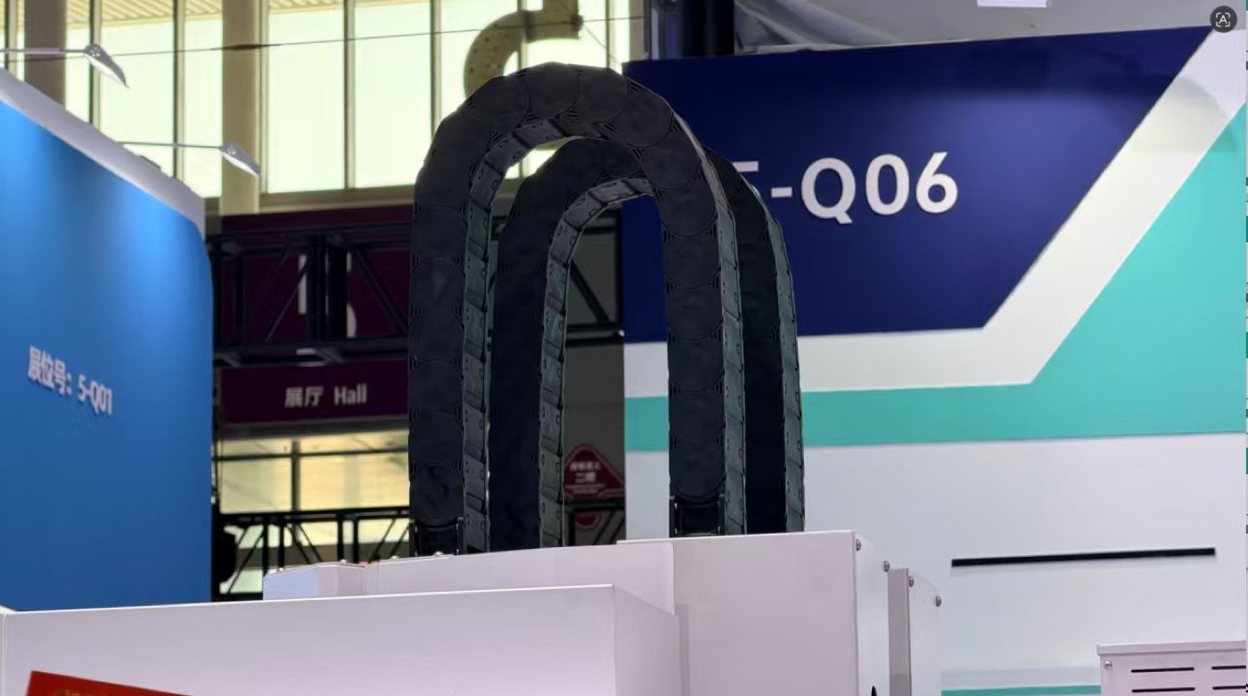
Defining Large Format
Size is not a marketing category. For a cable carrier, a machine tool becomes "large format" as soon as one of four thresholds is crossed, and each threshold changes a different part of the design.
- Travel above 10 m. The upper run can no longer be cantilevered; it must be supported, guided or made to roll. Wear changes from an incidental effect to the dominant life factor.
- Gantry width above 3 m. One chain can no longer serve the whole beam without being pulled sideways by any skew in the structure, so the layout becomes multi-chain.
- Bundle weight above 25 kg/m. Chain section, pin loading and the tension at the fixed end all become structural questions rather than catalogue selections.
- Loop height above 600 mm. The carrier starts to dictate the machine envelope, the guarding and the working height of the operator, so it must be designed with the machine, not added to it at the end.
Below these limits, a standard catalogue selection with a sensible safety factor is the correct approach. Above them, the carrier behaves like a machine axis: it has mass, it has a natural frequency, it grows with temperature and it needs alignment to a specification.
What Actually Changes at Scale
| Parameter | Small machine | Large format | What it forces |
|---|---|---|---|
| Travel | 1–3 m | 10–60 m | Guided trough, roller or driven system |
| Chain mass | 2–5 kg/m | 15–40 kg/m | Higher fixed-end tension, mechanical handling plan |
| Cable mass | 3–8 kg/m | 20–60 kg/m | Larger section, roller support, careful strain relief |
| Loop height | 150–300 mm | 600–1500 mm | Machine envelope and guarding redesign |
| Lateral tolerance | ±3 mm | ±1 mm over the full run | Laser or wire alignment, not tape measure |
| Thermal movement | Negligible | 2–5 mm over 20 m | Slotted or sliding fixed bracket |
The pattern is consistent: every parameter that is a detail on a small machine becomes a specification item on a large one. The failures seen in the field on large machines are almost never chain breakage. They are misalignment, thermal binding, trough deflection and cables that were never rated for the cycle count.
Long Travel: Gliding, Rolling or Driven
Three systems cover the whole range, and the choice is decided by travel, speed and duty cycle together.
- Gliding. The upper run slides on the lower run. Simple, quiet and cheap, and adequate up to roughly 30–40 m of travel at moderate speed and low duty cycle. Sliding friction is the limiting factor: the chain wears where the two runs touch, and wear accelerates with speed and with the weight of the bundle.
- Rolling. Rollers are fitted between the upper and lower runs so the chain rolls instead of sliding. Friction drops sharply, drive power and wear drop with it, and this is the standard answer for travel beyond 40 m or for continuous duty at speed. The cost is a taller chain section and more parts to inspect.
- Driven or pushed. The chain is pushed from the fixed end by a drive, or carried on a powered carriage. Used where the moving mass must be kept low or the chain must remain under control at very high speed. It needs its own control logic and is a machine-level decision, not a carrier accessory.
A common mistake is to specify a gliding chain for a 45 m press line because it worked on a 12 m machine. The mechanism is the same; the wear rate is not. Ask for the wear calculation in metres of travel per year, not "suitable for long travel".
Trough Geometry for Long Runs
On a long machine the trough is a structure in its own right, and most chain running problems start there.
- Width. Allow at least 10 mm clearance each side of the chain, and 15–20 mm on runs over 20 m where thermal movement and trough deflection accumulate.
- Wall height. The side walls must be tall enough to keep the chain centred even when the bundle pulls it sideways at maximum acceleration. As a rule the wall should reach at least the height of the chain in the trough, plus 20 % on wide gantries.
- Base flatness. ±2 mm per metre, and a cumulative limit of about ±5 mm over any 10 m. A trough that sags in the middle makes the chain climb one wall at mid-stroke and the other at the ends, which is exactly the wear pattern that shortens life.
- Joints. Trough sections must be aligned at the joint, not just bolted. A 1 mm step at a joint is a wear point that appears within weeks. Use dowels or a machined lap, and check every joint with a straight edge.
- Drainage and chips. Slots or holes at the lowest point, never on the running surface. Coolant pooling in a trough is the most common cause of premature pin wear on large machining centres.
Alignment Over the Full Stroke
Alignment tolerance scales with length, and the method has to scale with it. A tape measure and a plumb line are adequate on a 2 m machine and useless on a 30 m one.
- Set the trough with a laser or a tensioned wire, referenced to the machine guideways rather than to the floor.
- Check the lateral offset at three positions: both ends of the stroke and the middle. The middle is where a sagging trough shows up.
- The fixed bracket and the moving bracket must be coaxial within about 2 mm, and the chain must enter and leave both brackets without a lateral kink.
- Run the axis slowly by hand or at 5 % feed and watch the chain at the fixed bracket. A chain that shifts sideways there will shift further at production speed.
- Re-check after the machine has run for a full shift and reached thermal equilibrium. Cold alignment is necessary but not sufficient.
Sag, Support and Pretension
Long chains sag, and the question is where the sag is allowed to appear.
- On a horizontally running chain, the upper run is supported by the lower run and sag is not an issue. The trough base carries the load instead, which is why base flatness matters more than chain stiffness.
- On side-mounted and vertical arrangements, the unsupported span between supports is the critical number. Support every 1.5–2 m, and closer where the bundle is heaviest.
- Do not pretension a gliding chain to remove sag. Pretension increases the load at the fixed bracket, encourages the chain to lift off the trough and does not improve running behaviour.
- Leave the chain free to move longitudinally at the moving end within the bracket's designed travel. A rigidly clamped moving end on a 30 m machine turns thermal growth into a lateral force.
Multi-Chain Layouts on Wide Gantries
On a gantry wider than about 3 m, one chain per beam is the normal answer, and the reasons are structural rather than cosmetic.
- Skew tolerance. Two beams that can move relative to each other need two chains with independent troughs. A single chain spanning the gantry is loaded by every skew movement and will fail at the bracket.
- Load balance. Place the brackets symmetrically about the carriage centre of mass, then verify the calculated pull of each chain at maximum acceleration. A difference above about 15 % should be corrected by redistributing cables between the chains.
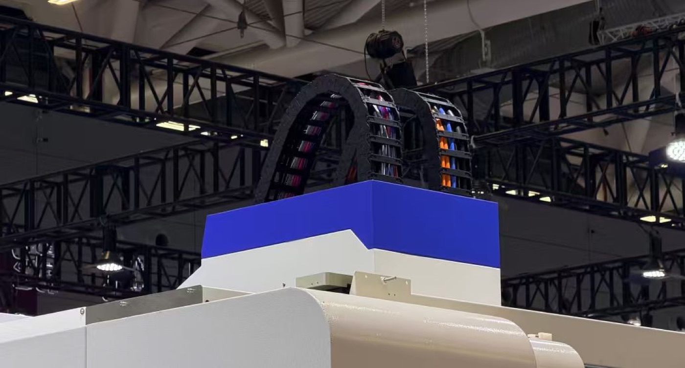
- Functional split. Put drive and spindle power on one chain and encoder, sensor and fieldbus cables on the other. The separation is worth more on a large machine than on a small one, because cable lengths are longer and induced noise is proportional to length.
- Redundancy. Where a carrier failure stops a whole line, a two-chain layout lets essential services keep running while one chain is replaced.
Cable Selection at Long Travel
On a large machine the cables, not the chain, usually set the loop height and the weight.
- Use continuously flexing cable rated for the actual travel and cycle count, and ask for the manufacturer's torsion and bend test data at the radius you intend to use, not the catalogue minimum.
- Bend radius: at least 7.5 × cable diameter for power cables and 10 × for encoder and bus cables in continuous duty. On a large machine the cost of a bigger radius is machine height, so this is a real trade-off to make early.
- Weight per metre is the design driver. A 40 m chain carrying 40 kg/m of cable has 1.6 t of cable in motion; acceleration forces and fixed-end tension follow directly from that number.
- Fill the cavity to about 60–70 % of cross-section and no more than 80 % of width. Overfilled chains on large machines wear at the separators first.
- Clamp both ends with proper strain relief, and leave a service loop. Cables that are clamped at one end only creep along the chain and fail at the clamp.
Thermal Growth and Structure Movement
A 20 m steel trough grows about 2.4 mm for a 10 K rise; an aluminium one grows about 4.6 mm. That is enough to bind a rigidly fixed bracket and to push a chain against a trough wall.
- Fix the trough at one point only, preferably near the machine's thermal centre, and let the rest of the run move in slotted holes.
- Use a sliding or slotted fixed bracket so that thermal movement appears as sliding, not as force on the chain.
- Do not weld trough sections continuously over a long run. Bolt them with lap joints that can accommodate movement.
- Check foundation settlement separately. A trough that was straight at installation and is bowed two years later has usually moved with the floor, not with the temperature.
Handling, Installation and Access
A 40 m chain at 25 kg/m weighs a tonne. Handling is part of the design, not a site problem to be solved on the day.
- Install in segments on temporary rollers, then join. Never lift a long chain by its end links; use the designated lifting points or a spreader.
- Plan the access before the guarding is designed. Inspection of a chain at mid-stroke on a 30 m machine needs a walkway, a removable panel or both.
- Keep a small spares kit on site: links, separators, strain relief clamps and one trough joint. On a large machine a two-day parts lead time is a two-day stop.
- Mark the trough at the mid-stroke position. It makes every future alignment check repeatable and takes seconds instead of an hour.
Commissioning and Baseline Records
Large carriers fail slowly, and the only way to see it coming is to record a baseline while the machine is new.
- Run ten full cycles at low speed and confirm the chain stays centred in the trough for the whole stroke.
- Run thirty minutes at production speed and acceleration, then measure chain surface temperature and look for wear debris in the trough.
- Check that cables move freely at both ends and that no cable is being pulled taut at either extreme.
- Record loop height, trough lateral offset at three positions and fixed bracket position. Photograph the chain at both ends of the stroke.
- Repeat the same measurements after the first 500 hours and once a year. A trend is worth more than any single reading.
Specification Checklist
- Travel, speed, acceleration and duty cycle, with the cycle count per year.
- Complete cable list: type, outer diameter, weight per metre, minimum bend radius, flex rating.
- System choice: gliding, rolling or driven, and the reason for it.
- Chain series, inner height, inner width, bend radius and number of chains.
- Trough: material, section, length, joint detail, drainage and clearance.
- Alignment specification and the method used to achieve it.
- Thermal movement allowance at the fixed bracket.
- Access for installation and for inspection at mid-stroke.
- Spares list and the baseline record to be taken at commissioning.
Answer these nine before the machine guard is drawn, and the carrier will sit quietly inside the machine for its whole life instead of becoming the item that everyone remembers.
Specifying a cable carrier for a large-format machine?
Send us the stroke, the cable and hose list with diameters, the weight per metre and the bend radius you need. Our engineers reply with the chain system — series, inner height and width, dividers, strain relief and a guide trough if required — usually within one working day.
Twin Cable Carriers on One Axis: Layout, Balance and Cable Split
Related Article